|
|
ICT / MDA Loaded Board Electrical Test Systems
Testronics Architecture Details
for 400 Series Electrical Test Systems
Architecture Specifics
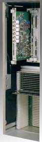
- The 406 uses a VME style backplane which has been optimized for In-Circuit measurements. The backplane accepts Testronics produced system cards and modules.
- The interface between the PC computer and the test system is high speed parallel printer port. By using the printer port, the interface is standardized, allowing the implementation of many different types and manufacturers of PCs
- There are three types of Testronics designed cards used on the 406 test system:
a. System control cards
b. Switch matrix cards
c. Option cards
| System Control Cards Consist Of: |
- System Block Diagram, which sources and measures the voltages and currents applied to the UUT during the MDA / ICT test. It supports true 6 wire measurements. The SMU is programmable up to 10 Volts AC / DC and up to 5 mAmps, (100 mAmps on the guard). The SMU can source voltage / measure current or source current / measure voltage. The current and voltage compliance limits are fully programmable as well.
- The Host Receiver card is the interface between the PC and the other system cards.
- The Control Card has two functions. It acts as a multiplexer between the SMU and certain switch matrix cards. In most applications, there is one Control Card required for each card cage of switch matrix cards. The second function of the Control Card is to interface to the external switches, lamps and indicators. In a high pin count, multiple Switch Card cage system, the first Control Card handles all of the external interfacing.
|
Switch Cards can contain any combination of five different types. There will be certain system limitations based on specific card combinations.
| Switch Matrix Card Types: |
- Opt. 46-SS - 10 volt Solid State, 6 Wire Switch Matrix Card, SMD Version. This card uses analog switches to create a high speed, low cost matrix. A big advantage is on high pin count systems, 5k – 20k points. The test point density is very high due to the 100% use of SMD components.
- Opt. 46-LV - 10 volt Solid State, 6 Wire Switch Matrix Card, Standard Version. This card also uses analog switches to create the switch matrix, but is packaged in a standard VME style card. The large card format allows for quick and easy board changeout and repair.
- Opt. 46-HV - Combination 10 volt Solid State Switch / Isolation Relay, 6 Wire Matrix. A relay is placed in series with the output of each solid state analog switch. There are 64 test points per switch card, therefore there are 64 relays used, one for each test point. This provides the ability to isolate the 10 volt electronics from the UUT. This is necessary when the UUT is powered up with external supplies to a voltage greater than 10 volts.
- Opt. 46-3W - 3 Wire Relay Based Switch Matrix Card. This card is a true relay based matrix that allows any signal present on the 3 source leads of the analog measurement buss to be directed to a specific test point, (or any combination of test points). This card is typically used to keep overall system costs lower at the expense of ohmic measurements less than 1 ohm. 4 & 6 wire Kelvin measurements are normally not required across the complete matrix. Typical application would be to have several of these 3 wire cards plus just one of the 6 wire Kelvin cards.
- Opt. 46-6W - 6 Wire Relay Based Switch Matrix Card. There are 6 separate relays for each test point with this style of switch matrix card. Any signal present on the 6 wire analog measurement buss can be switched to any combination of test points. Source, Source Sense, Return, Return Sense, Guard and Guard Sense are the analog buss lines available. This card provides the most flexibility of any of the switch matrix cards offered.
|
| Option Card Types: |
- Opt. 24 - 24 Channel Relay Driver. This option card provides 24 N/O program controllable relay contacts to the user. 5 of the contacts can also be used in a N/C configuration. There are 8 digital TTL input bits also available for program use. 8 bit words or individual bits can be read back by test program. The 24 relay channels can be converted to 24 digital TTL bits by leaving the relays off and taking their coil drivers, (which are TTL), directly off the board. This is a factory option and needs to be defined at time of order. Cards with relay contacts can be mixed together with cards without relays. Multiple 24 channel cards can be added together to increase the total I/O capability.
- Opt. HP – Hewlett Packard TestJet is an option card that resides in the PC. TestJet is a technique used to detect opens on bussed SMD leads using a capacitive coupling method. This is a patented technique and the option comes with a license from HP for it’s use.
- Opt. 46-INST - Instrument Matrix Card. This card provides the ability to switch external instruments onto the 6 wire analog measurement buss. There are 64 external channels thereby creating a 64 x 6 matrix. The test language supports program control of each of the channels.
- Opt. 38 - IEEE Integration. The test language supports the addition of external IEEE instruments and power supplies. Several functions facilitate the initialization, setup, and read back of the IEEE instruments.
|
Learn More
For additional information about systems that contain the Testronics 406 architecture, click one of the model-specific links below:
Model 406A --Low Cost Manufacturing Defects Analyzer
Model 406C --Analog In-Circuit Tester
For personal assistance regarding these products, or any other, call 1-972-542-3111, email info@testronics.com, or click the link provided below.
|