Automated Optical Inspection Systems
Benchtop AOI / Tabletop AOI / Desktop AOI
Testronics 500 Series AOI
Overview of Features and Benefits
The table below was designed to show the features and benefits of Testronics' Benchtop / Tabletop / Desktop Automated Optical Inspection (AOI) product family:
 |
 |
 |
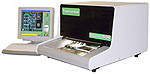
| Model 504 Benchtop AOI System |
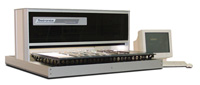
Model 506 Backplane / Backpanel Large Assembly AOI System |
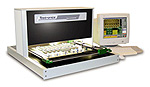
Model 505A |
| Features | Benefits |
| Adjustable Resolution | The Testronics 500 series AOI systems can be optimized for the customer’s inspection requirements today, balancing inspection speed with component defect coverage. Later, when their technology changes, such as requiring 0201’s or .3mm QFP solder and lead inspection, a simple adjustment allows the resolution to be changed. This insures their system will not be obsolete when their board technology changes. The Testronics AOI systems are adjustable from 23 microns / pixel to 9 microns / pixel |
| Free software updates | AOI systems are 90% software. By providing free, unlimited software updates, the original customer is able to keep their Testronics AOI systems at the most current generation as no additional fees or annual licenses are required. The latest software is available as a download for free. |
| CAD Programming | By using the ASCII CAD data, an inspection program can be created quickly and accurately. A CAD translation utility is included in the software at no charge. |
| Datalogging of all measurements | The Testronics 504, 505A, & 506 AOI Systems will store all inspection measurement data, regardless of pass or fail. This data is stored in a Microsoft ACCESS database, therefore easily accessible through many different software packages such as excel, word, access, etc. Component positions are also recorded so that the data can be used to verify the repeatability of the placement machines. Other AOI systems typically only record the failures and only the number of times they fail. Virtually no measurement details are recorded on the other systems. The Testronics AOI Systems provide the most inspection information of any AOI system available. |
| Operator review screen that flashes between good and bad images | The Testronics AOI will display to the operator a very large image of the failing component. The operator can then have the system toggle the display between the good image and the failing image. Other AOI systems display the faulty image and a smaller piece of the good image. The operator must then move their head to look between the two images and try to see what is actually different. The ability to toggle between the two images creates an animated movement for the operator to quickly and easily review the fault. This technique reduces operator fatigue and reduces the chance the operator will click through the defects saying they are false failures. This is a common problem on the other AOI systems. The feedback we receive from the operators is that they prefer the Testronics review screens over the other systems. And as the operator is the one who uses the system 100% of the time, we consider this a very important point. |
Most inspection algorithms of any AOI |
The Testronics AOI systems have 7 different algorithms. This provides the customer with the most inspection capability and highest repeatability of any AOI. We have three versions of pattern matching algorithms, three versions of profiling algorithms, a subtractive algorithm, and a rules based algorithm. The pattern matching algorithms we use are very similar to facial recognition algorithms and are used for solder joint inspection and component text. The profiling algorithms are similar to those used in the Agilent 5DX x-ray systems and are used to detect cracks on components and bridges on fine pitch devices. The subtractive algorithm is used to inspect for variations in color. The rules based algorithm is for IC leads and bridging. |
| Visual Basic scripting option | The Testronics AOI provides the ability create a fully interactive AOI system by using the optional Visual Basic Scripting Language. An example of such an application would be the need to inspect an assembly, and then power it up to verify the LCD or display worked. A similar application would be to power up the assembly to verify the correct color of LEDs had been placed. No other AOI has this ability. Another application of Scripting would be the implementation of an Auto-Flip sequence. The system will pause upon completing the inspection of the assembly’s top, and then prompt the operator to flip the board so that the bottom can be inspected. The software will automatically select the bottom inspection program and continue the inspection. |
| Off-line programming station | Because the Testronics AOI Systems use complete images, (instead of pieces of images used with other AOI systems), full off-line programming and program tuning is possible. |
| Skip marks and X-Outs are fully supported for panel inspection | The Testronics advanced AOI software will automatically identify skip marks on a panelized board. The software will eliminate the inspection results of the skipped boards so that the operator does not have to review them. |
| High frequency white lighting | The Testronics AOI uses two, high frequency florescent linear tubes as lights. White light provides the highest flexibility of any lighting solution. Other AOI systems use monochromatic LED lights. These severely limit the capabilities of the AOI. Because the Testronics AOI uses white light, all colors are available either combined or individually. Each algorithm can select all colors or just Red, Green, Blue, Hue , Saturation or Luminance. By selecting the specific color channel or attribute, a higher degree of program stability can be achieved. Additionally, replacement florescent lights are available at a very low price locally. |
| Color print out of errors | The Testronics AOI has the ability to print out not only a description of the defect, but an actual color picture of the defect and its surrounding components. This capability proves to be very valuable for the repair and rework technician. Very few AOI systems provide print outs, and even fewer provide color pictures of the defects. |
| Full board view of error location | Most other AOI systems only show the operator an image of the defect. On a complex assembly or panelized board, the operator has much difficulty locating the specific defect’s location. With one click, the Testronics AOI System displays an image of the complete board with the defect highlighted with large yellow lines. The operator then can easily locate the defect within seconds. |
| True references images | There is a very different paradigm between the Testronics AOI and other AOI systems. Other systems create a "synthetic" library that contains the picture of only one component. They then use this picture to inspect all other components. One example is that all capacitors are inspected against the same “master” image. C1 is never inspected against C1 of the golden board. It is only inspected against the “master” image. Another example: They will store only the picture of one pin on an IC and use this as a “master” image. They then inspect all other IC pins against this single “master” image. With fine pitch and lead free, this technique does not work reliably. You must go to a technique such as used on the Testronics AOI. We do not create a synthetic master image. The Testronics AOI will inspect each component against the reference component on the golden board. We inspect all of the board's C1's against the C1 present on the reference board. We then inspect all C2's against the reference board's C2, etc. This is important on solder inspection as the solder fillet depends on the pad size and if a trace is present. In other words, we maintain the "context" of the component. Our technique takes into consideration surrounding items that affect the component's solder fillet and placement. Small pad = less fillet; large pad = more fillet. Large ground trace to a large pad cause more component shift, plus a lot of extra solder. And once you get into lead free, you cannot use a single image to inspect all IC leads. Pin 1 will look much different than pin 173 of a .4mm QFP. You must inspect pin 1 against pin 1 on the reference board, pin 2 against pin 2, pin 208 against pin 208. Creating a "synthetic" image of pin 1 and applying it to all other pins requires you to open up the tolerances so much that most solder defects are missed. |
|
||||||||||||||||||||||||||


Learn More
For additional information about the Testronics 500 Series click one of the model-specific links below, or explore the resources section of this page:
Model 504 --Benchtop AOI System
Model 505A --Advanced AOI System
Model 506 --Backplane AOI System
For personal assistance regarding this series, or any Testronic product, call 1-972-542-3111, email info@testronics.com, or click the link provided below.
Request More Information